Check out our White Paper Series!
A complete library of helpful advice and survival guides for every aspect of system monitoring and control.
1-800-693-0351
Have a specific question? Ask our team of expert engineers and get a specific answer!
Sign up for the next DPS Factory Training!
Whether you're new to our equipment or you've used it for years, DPS factory training is the best way to get more from your monitoring.
Reserve Your Seat Today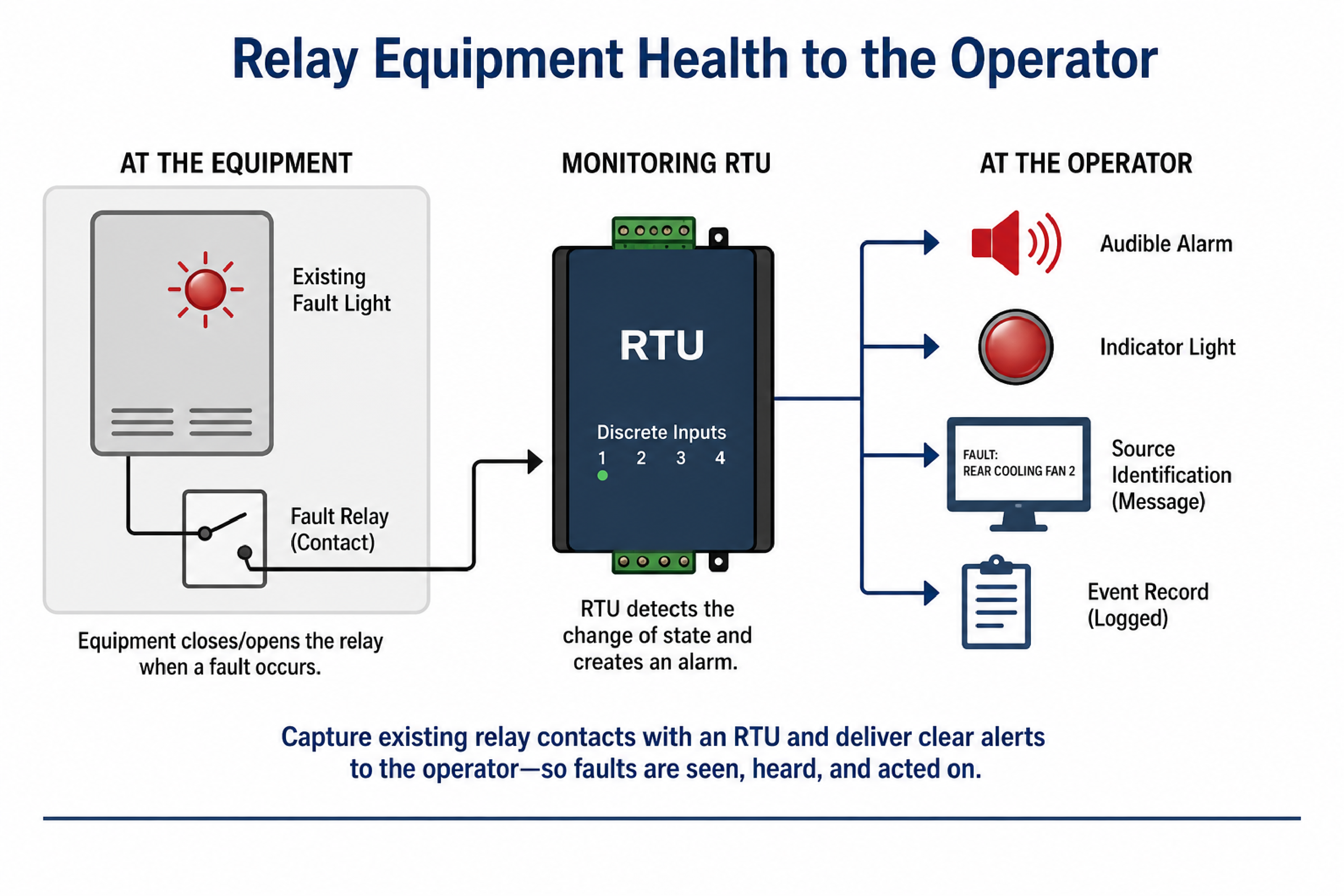
Relaying equipment health to an operator means taking a fault or status signal that a machine already produces - often a simple relay contact - and delivering it to the person who needs to act on it, in a place where they will actually see or hear it. A fault light mounted on the equipment itself is useless if the operator is in a different compartment and never looks at it.
This article explains how to extend an existing equipment health indicator into a clear operator alert, why a local-only fault light falls short in mobile and distributed equipment, and how to design a monitoring tie-in when the application sits outside a standard catalog product. It is written for engineering and operations teams in transportation, utility, and industrial settings where a missed equipment fault has safety or regulatory consequences.
Contact-closure monitoring is the practice of detecting the open or closed state of a relay or switch contact and reporting that state as an alarm. Most equipment that has a status light or a fault indicator is already driving that indicator with a relay, which means the same contact can usually be tapped to feed a monitoring device.
A remote telemetry unit (RTU) is the device that reads those contacts and converts them into alarms. When a piece of equipment closes or opens a contact to signal a fault, an RTU discrete input sees the change of state and can act on it - sounding an audible alert, lighting an indicator, sending a message, or forwarding the event to a central system. The key point is that no new sensing has to be invented: the equipment already knows it is faulted, and the relay it uses to show that locally is the signal to capture.
This is why tying into an existing health-indicator relay is often the cleanest path. The equipment vendor has already defined what a fault looks like as a contact state. Monitoring simply makes that state visible somewhere more useful.
A local-only fault indicator is a status light or display mounted on the equipment itself, visible only to someone standing at that equipment. In mobile or distributed systems, the person responsible for responding is rarely standing there, so the fault can go unnoticed until it causes a larger failure.
Consider equipment mounted at the rear of a vehicle or at the far end of a facility, with the operator stationed elsewhere. The indicator may be working perfectly, but:
The operational goal is to move the alert from where the equipment is to where the operator is. That single change - relaying the indication to the operating position - is what turns a passive light into an actionable alert.
Capturing an existing relay means wiring a monitoring input in parallel with, or from, the same contact that already drives the equipment's status light, so the original function is unchanged. This is a common and low-risk integration because it does not alter how the equipment operates.
A typical approach:
Because units in the NetGuardian product family provide discrete inputs along with control relay outputs, a single device can both read the equipment's fault contact and drive a local audible and visual alert at the operating position. Where more than one indicator exists - for example, two separate sensing elements each with its own health contact - each contact lands on its own discrete input, so the system can tell the operator which specific element failed rather than just signaling a generic fault.
An operator alert is the combination of outputs that tells a person a fault has occurred and, ideally, what failed. The most effective alerts use more than one sense and identify the source of the problem.
Useful elements, in rough priority order:
The audible and visual alerts are usually the must-haves; the source-identifying message is a strong nice-to-have. When choosing hardware, matching the input and output count to the number of fault contacts and the number of alerts you need to drive is what keeps the design appropriately sized - the same discipline described in choosing the right RTU.
Power and network constraints are the practical limits on where a monitoring device can be installed and how it communicates, set by the available voltage and the reach of the local network. In vehicles and remote enclosures, these constraints often drive the hardware selection more than the alarm logic does.
Common field realities to design around:
| Constraint | Design Implication |
|---|---|
| DC-only power in the equipment area | The RTU must accept the available DC voltage directly, or a power converter must be added. Equipment bays often have DC but no AC outlet. |
| AC available only at the operating position | Output devices near the operator may run from AC, while the sensing RTU near the equipment runs from DC. |
| Wireless coverage that fades with distance | A range extender or a wired link may be needed to reach equipment at the far end of a vehicle or site. |
| Need for an alternate communication path | Some RTU models support dual network connections so a single link failure does not blind the system. |
The wireless point deserves attention. If the alert depends on a network link that weakens with distance, the link itself becomes a failure point. Designing for a backup path, or confirming the device reports a fault when it loses its connection, is part of maintaining visibility when the network path is degraded. An alert system that silently stops working is worse than no alert system, because it creates false confidence.
A semi-custom monitoring solution is a design that starts from standard hardware and adapts it to an application that is not a direct catalog match, without becoming a fully bespoke build. Many transportation and industrial monitoring needs fall into this category: the requirement is specific, but the building blocks are standard.
A workable path from pilot to fleet:
The economics improve with quantity. A small initial order carries more of the engineering effort per unit, while a larger fleet rollout spreads that effort and can reach better pricing. When an application sits outside the standard catalog, it is worth confirming feasibility against the available product families before committing to a custom path, because a standard unit configured correctly often does the job.
Usually yes. The relay or contact that drives the existing status light can typically be brought into a monitoring input in parallel, so the original indicator keeps working while the new system also sees the fault. This is a low-risk integration because it does not modify the equipment's own logic.
Land each component's health contact on its own discrete input. Because each input is monitored separately, the system can drive a distinct message or indication for each one, so the operator knows which element faulted rather than seeing a single generic alarm.
Choose an RTU that accepts the available DC voltage directly, or add a power converter. Many field enclosures and equipment bays provide DC but no AC outlet, so confirming the input voltage range early avoids a redesign later.
Design so the loss of a link is itself an alarm, and consider a dual-path or extended-range connection where coverage is weak. An alert system that fails silently gives false confidence, so detecting its own loss of connectivity is an important requirement.
It is often semi-custom: standard RTU hardware adapted to a specific monitoring and alerting requirement. Confirming that a standard unit, configured correctly, can meet the need is the first step before considering a fully custom solution.
Generally yes. A small initial deployment carries more engineering effort per unit, while a larger rollout spreads that effort across more units and can qualify for better pricing. Proving the design on a pilot set first reduces risk before scaling.
If a critical piece of equipment signals its own faults only with a local light that the operator never sees, the fix is to relay that indication to where it will be noticed - with an audible alert, an indicator, and a message that names what failed. DPS Telecom regularly adapts standard RTU hardware to monitoring applications that fall outside the catalog, including tie-ins to existing relay contacts and designs that account for real-world power and network limits. Get a Free Consultation to discuss your application, or call 1-800-693-0351 or email sales@dpstele.com to review feasibility and next steps.

Andrew Erickson
Andrew Erickson is an Application Engineer at DPS Telecom, a manufacturer of semi-custom remote alarm monitoring systems based in Fresno, California. Andrew brings more than 19 years of experience building site monitoring solutions, developing intuitive user interfaces and documentation, and opt...